Optical Elements of the Schmidt-Cassegrain
Telescope
A telescope is a group of optical elements that collects
light and focuses it for
observation by an eyepiece or
some other imaging device. There
are two types of optical
elements: mirrors and lenses.
Mirrors reflect light and lenses
refract, or bend light. The
Schmidt-Cassegrain telescope
uses both mirrors and lenses.
The diagram below shows a
cross-section of a Schmidt-Cassegrain.
In this telescope, light first
passes through the corrector
lens, and then reflects off the
primary mirror. Finally, it
reflects off the secondary
mirror and comes to a focus at
the focal plane.
Optical
Coatings
The purpose of a telescope is to
collect as much light as
possible. The amount of light
collected affects the brightness
of the resulting image.
Unfortunately, there are sources
of light loss at each optical
surface, and within each lens.
Fortunately, we can design
optical coatings and choose lens
materials that minimize the
amount of light lost to these
sources.
Optical
coatings are very thin layers of
material that are applied to the
glass in a process called
'vacuum deposition'. The
physical properties and
thickness of each layer in the
coating, as well as their
orientation with each other and
the glass to which they are
applied, determine how well they
will do their job.
Since the
function of a mirror is to
collect light by way of
reflection, we use highly
reflective metallic coatings on
these optical elements. A mirror
without coatings reflects about
4% of the light that hits its
surface. A mirror coated with
standard Aluminum coatings
reflects about 86 - 88%, and a
mirror coated with StarBright
XLT reflects 95%.
Light traveling
through a lens is a little more
complicated. In this case, light
is lost to both reflection
and absorption.
When light first strikes an
uncoated lens, about 4% is
reflected back and never has the
chance to make it through. Some
of the remaining 96% will be
absorbed on its way through the
glass, and then the second lens
surface reflects another 4%. To
minimize unwanted reflection,
dielectric materials are used in
pairs of alternating high and
low refractive index. A good
anti-reflection (A/R) coating
for telescope lenses is one that
will deliver very low, very
'flat' reflectance across the
entire visible spectrum.
Although A/R
coatings can dramatically reduce
the amount of light lost to
reflection, no optical coating
can reduce the amount of light
lost to absorption within the
glass. To reduce this source of
light loss, it is important to
choose a glass that absorbs as
little light as possible.
For many A/R coating
applications, it is standard to
measure the reflection of the
coated surface and to ignore the
amount of light that is being
absorbed by the glass. But for a
telescope lens, stating how well
an A/R coating suppresses
reflection without also
revealing how much light is lost
to absorption within the glass
can be quite misleading. For
this application, actual
transmission, which accounts for
light lost to both sources,
should be measured directly. You
can learn more about how we did
these measurements in the
section titled
Our
Measurements.
Telescope System Transmission
System transmission is the
percentage of light that arrives
at the focal plane compared to
the light that enters the
telescope, and is calculated by
taking the product of the
corrector lens transmission, the
primary mirror reflectance, and
the secondary mirror
reflectance. Here is an example;
if the corrector lens transmits
92% of the light, and the
primary and secondary each
reflect 89% of the light, then:
Total System
Transmission = .92 * .89 * .89 =
.73 (73%)
StarBright
XLT — An
Optical
System
Breakthrough!
Celestron has brought its renowned StarBright technology
to an
even
higher
level of
light
transmission
with the
introduction
of our
new
optional
StarBright
XLT High
Performance
Optical
Coating
System.
StarBright
XLT
Optical
System
Design —
You’ll
See The
Light.
One of
the most
important
factors
in the
evaluation
of a
Schmidt-Cassegrain
telescope’s
optical
system
performance
is its
transmission
— the
percentage
of
incoming
light
that
reaches
the
focal
plane.
The
design
of the
XLT
System
accomplishes
two
crucial
objectives:
Develop
a
coating
system
that is
optimized
for
visual
use and
for CCD/Photographic
imaging.
The
StarBright
XLT
System —
What
Makes It
Different
Makes It
Better
There
are
three
major
components
that
make up
our
StarBright
XLT high
transmission
optical
system
design:
1.
Unique
enhanced
multi-layer
mirror
coatings
Our
mirror
coatings
are made
from
precise
layers
of
Aluminum
(Al),
SiO2
(quartz),
TiO2
(Titanium
Dioxide),
and Si02.
Reflectivity
is
fairly
flat
across
the
spectrum,
optimizing
it for
both CCD
imaging
and
visual
use.
2.
Multi-layer
anti-reflective
coatings
Made
from
precise
layers
of MgF2
(Magnesium
Fluoride),
and HfO2
(Hafnium
Dioxide)
A rare
element
costing
nearly
$2000
per
kilogram,
Hafnium
gives us
a wider
band
pass
than
Titanium,
used in
competing
coatings.
3. High
Transmission
Water
White
glass
Celestron
Schmidt-Cassegrain
optical
systems
with
optional
StarBright
XLT
coatings
use
Water
White
glass
instead
of Soda
Lime
glass
for the
corrector
lens.
Water
White
glass
transmits
about
90.5%
without
anti-reflective
coatings.
That is
3.5%
better
transmission
than
uncoated
Soda
Lime
glass.
When
Water
White
glass is
used in
conjunction
with
StarBright
XLT's
anti-reflective
coatings,
the
average
transmission
reaches
97.4% —
an 8%
improvement!
These
three
components
of our
StarBright
XLT
coatings
result
in one
of the
finest
coatings
available.
The peak
transmission
for the
systems
is 89%
at 520
nm. The
overall
system
transmission
is 83.5%
averaged
over the
spectrum
from 400
to 750
nm. The
plot
below
shows
the
entire
system
transmission
over the
spectrum.
|
|
| This plot is obtained by measuring the reflectivity of the secondary mirror and the primary mirror and measuring the amount of light transmitted through the coated corrector lens. Each of those values are multiplied together calculate the system transmission. The overall system transmission peaks at 88.9% while the average transmission is 83.5% over the spectrum from 400 to 750nm. |
|
*Percent differences are calculated by taking the comparison data percentage divided by the baseline data. Example: Measured average system transmission for current StarBright is 72%. XLT average system transmission is 83.5%. 83.5% divided by 72% = 1.16 or 16% improvement. Measurement results are rounded to the nearest whole percentage.
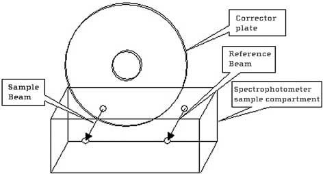
Testing Methods:
Total telescope light throughput can be measured in two different ways; either by measurement of the assembled optical system, or by measurement of the reflectance of each mirror (or reflective element), and the transmission of each refractive element in the optical path. In the case of a Schmidt Cassegrain telescope, there are two reflective elements (the primary and secondary mirrors), and one refractive element (the corrector plate, or Schmidt Corrector). See diagram below:
Assembled Telescope vs. Individual Optical Element Analysis:
To measure the throughput of the assembled telescope, a beam of light is passed through the telescope and compared to a beam of equal intensity light passing through air only. Total telescope throughput is then the ratio of light intensity measured through the telescope divided by the light intensity measured through air. This is easily said, but very challenging to execute correctly. Great care must be taken to ensure that the reference beam is of constant intensity, and that its light is collected in a manner which does not bias the results. Errors introduced by beam geometry (f ratio) at the entrance to the detector, less than perfect alignment of the optical elements, including placement and dimensions of internal light baffles, will tend to reduce the intensity of light measured through the telescope.
The second method of measuring total telescope throughput, by spectrophotometric analysis of each element in the optical path, is not susceptible to these sources of error. Furthermore, individual element analysis provides specific information about each optical element, while measuring the throughput of the assembled optical tube does not. Results obtained in this manner represent an upper limit to the actual throughput of the assembled telescope. Total Telescope Throughput (%TT) is less than or equal to Corrector Plate Transmission (%TC) times Primary Mirror Reflectance (%RP) times Secondary Mirror Reflectance (%RS).
Corrector Plate Transmission (%TC):
We use a Shimadzu UV1601 spectrophotometer for analysis of corrector plate transmission. This is a double beam instrument with a spectral range of 190 to 1100nm. Transmission data is typically collected in the visible region from 400 to 750 nm. Small samples of corrector material called witness plates are included in each corrector coating run. In order to minimize handling and the possibility of scratching a full size corrector plate, we use these witness plates to represent the transmission characteristics of our correctors.
Our instrument is capable, however, of measuring the transmission of correctors up to 8” diameter. If this is necessary, the corrector plate is measured at 4 points roughly 90° apart, and the results are averaged. Before and after each measurement, baseline (100%) measurements are made to ensure light source and/or detector drift is negligible.
Primary and Secondary Reflectance (%RP, %RS):
The preferred method of measuring reflectance of primary and secondary mirrors involves the use of witness plates as well. These are small (1” to 2” diameter) flat polished glass substrates, which are coated along with the primary and secondary mirrors. Since the coating process is the same, and the surfaces are equally well polished, the reflectance of the witness plate is the same as that for the primary and secondary mirror. The reasons for using flat witness plates are 1) the primary and secondary mirrors are not themselves subjected to a measurement process which can potentially cause scratches, and 2) very simple test methods and readily available reference standards can be used to measure the reflectance of flat surfaces.
Typically, the reflectance of a surface is measured against a standard reference of known reflectance. Our standard reference is an enhanced aluminum coated quartz flat, calibrated against a NIST (National Institute of Standards and Technology) specular reflectance standard. To measure the reflectance of a flat sample, the baseline measurement is made using this standard, and the reflectance of the sample is compared to this baseline. The sample reflectance factor (%RS) is equal to its reflectance relative to the reference standard (%RSR) times the reference standard’s known reflectance (%RR):
However, if the sample to be measured has a curved surface like a secondary or a primary mirror, and there is no witness plate available, then special care must be taken to ensure that the method used to measure reflectance is insensitive to this curvature. If we compared the reflectance of a curved surface directly to that of a flat reflectance standard, our results would not be accurate, since the converging or diverging beam generated by a curved surface would direct either less light (in the case of a secondary mirror), or more light (in the case of a primary mirror) onto the detector than was directed by the flat reference standard.
The most widely used tool for measuring the reflectance of curved surfaces is called an integrating sphere. This device collects and then measures the intensity of light in a manner which is insensitive to beam geometry, hence, insensitive to surface curvature of a reflective sample being measured. However, integrating spheres can be quite expensive, and they are time-consuming to set up and calibrate. We developed a method which is equally insensitive to surface curvature, but much less costly and time consuming to perform. We made our own reference standards from secondary and primary mirrors with the same surface curvature as those we wished to test.
We obtained samples of the secondary and primary mirrors which we wished to test, stripped the existing coating, and replaced it with one for which we also obtained flat witness plates. These flat witness plates were calibrated against a NIST specular reflectance standard. Since the flat witness plates were coated along with the curved samples, and since we have adequate data to show that our coatings are very uniform from part to part in any given coating run, we can apply this reflectance data to our curved samples. Using these curved surface reflectance standards we are able to measure other mirrors of the same curvature just as we use our flat reflectance standard to measure the reflectance of flat samples.
To perform these measurements, we use an Ocean Optics USB2000 Spectrometer with an LS-1 Tungsten Halogen Light Source. This is a single-beam instrument with a 0.3nm resolution, a scanning range from 340nm to 1024nm, and is equipped with a fiber optic curved-surface reflectance measuring probe.
Reporting the Data:
Collecting the data and reducing it to yield total telescope throughput (%TT) (system transmission) is simply a matter of multiplication. We find the average of each data set (%TC, %RP, and %RS) for each wavelength measured, and multiply them together.
Click here to return to Celestron price page |
|
|
|
|
|
|
|